MethodicConfigurator
ArduPilot Methodic Configurator User Manual
Overview
ArduPilot Methodic Configurator is a PC software designed by ArduPilot developers to simplify the configuration of ArduPilot vehicles. Its graphical user interface (GUI) manages, edits and visualizes parameter files, as well as uploads parameters to the vehicle. It automates the tasks described in the How to methodically tune any ArduCopter tuning guide.
This user manual gives a general overview of the software functionality. There are also quick start instructions, specific use case instructions, and frequently asked questions.
Table of Contents
- Step-by-Step Workflow
- Configuring multiple similar vehicles
- Flight-Controller Parameter Export
- MAVFTP File Browser
- Firmware Upload
- Customizing configuration steps (external document)
- Command Line Usage
- Troubleshooting
- Support (external document)
- Installation and Security (external document)
- FAQ (external document)
- Glossary
Before You Begin
⚠️ IMPORTANT: If you will connect a flight controller, connect it to the PC and wait at least 7 seconds before
starting the software. You can also work offline or create a project from a .bin log without connecting one.
💡 TIP: Have your vehicle’s component documentation ready (motor specifications, ESC type, etc.)
Step-by-Step Workflow
Don’t worry! It looks more complicated than it actually is. And you do not need to understand the diagram to use the software.
flowchart TD
    A[Start AMC] --> B{.bin log on command line?}
    B -->|Yes| M
    B -->|No| C

    subgraph "Step 1: Connect to Vehicle (optional)"
        C{Connect to Flight Controller?} -->|Yes| D{Auto-Detect?}
        D -->|Yes| E[Download FC Info and Parameters]
        D -->|No| F[Manual Connection]
        F --> E
        C -->|No, work offline| G[Continue without FC]
    end

    subgraph "Step 2: Select or Create Project"
        E --> H{Existing Project?}
        G --> H
        H -->|Yes| I[Open Vehicle Directory]
        H -->|No| J{Create from?}
        J -->|Configured FC, if connected| K[Create from Configured FC]
        J -->|Template| L[Select Template]
        L --> N[Create New Project]
        J -->|.bin log| M[Create from .bin Log]
    end

    subgraph "Step 3: Edit FC Components"
        O[Component Editor] --> P[Validate Components]
        P --> Q{Valid?}
        Q -->|No| O
    end

    subgraph "Step 4: Edit FC Parameters"
        R[Parameter Editor] --> S[Configure Parameters]
        S --> T{Advance how?}
        T -->|Upload to FC| U[Upload Selected Parameters]
        T -->|Skip or work offline| V[Skip Parameter File]
        U --> W{Experiment Required?}
        W -->|Yes| X[Close AMC]
        X --> Y[Perform Experiment/Flight]
        Y --> Z[Start AMC]
        Z --> AA[Read Results from FC]
        AA --> AB[Write Results to File]
        AB --> AC{More Files?}
        W -->|No| AC
        V --> AC
        AC -->|Yes| R
        AC -->|No| AD[Generate Summary]
        AD --> AE[Configuration Complete]
    end

    I --> R
    K --> O
    M --> O
    N --> O
    Q -->|Yes| R
    R -->|Edit vehicle components| O
If the diagram above does not display correctly look here
This section guides you through the complete configuration process. Follow these steps in order:
Preparation
- Collect your vehicle’s component documentation (motor specifications, ESC type, GPS Type, etc.)
- If using a flight controller, connect it to the PC via USB cable
- If connected, wait at least 7 seconds for the flight controller to fully boot
- Launch ArduPilot Methodic Configurator
Step 1: Flight Controller Connection
If the software successfully auto-detects your flight controller, it skips the connection selection window and downloads the flight controller information and parameters. You then select or create a project if needed (Step 2). If a project was supplied or found in the working directory, it proceeds directly to the parameter editor (Step 4).
The connection selection interface is only presented if auto-connection fails or if no flight controller is detected.
You can also continue without a flight controller and edit a project offline. With --bin-log, AMC skips the connection
and project selection windows, creates a project from the log, and opens the component editor (Step 3).
Flight Controller Connection Selection Interface
This interface allows users to select or add a connection to a flight controller if one was not yet auto-detected.
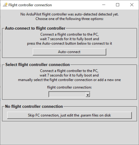
Flight controller connection selection window
It provides three main options for connecting to a flight controller:
Choose your connection method:
Option 1: Auto-connect to flight controller ⭐ Recommended for most users
This option automatically detects and connects to your flight controller.
- ✅ Use when: Your flight controller is connected via USB and powered on
- ⏱️ Wait time: Ensure 7+ seconds have passed since connecting
- 🔧 Troubleshooting: If auto-detection fails, try Option 2
Option 2: Select flight controller connection ⚙️ For advanced users
Manually specify your connection details.
- ✅ Use when:
- Auto-connect doesn’t work
- Using network connections (TCP/UDP)
- Multiple flight controllers connected
- A baudrate other than 115200 is to be used
- 📝 How to:
- Select existing connection from dropdown, OR
- Choose “Add another” to enter custom connection string
- For serial connection select the correct baudrate
- 💡 Examples:
- Serial:
COM3(Windows) or/dev/ttyUSB0(Linux) - Network:
tcp:192.168.1.100:5760
- Serial:
Connecting AMC through Mission Planner MAVLink forwarding
Use this setup to keep Mission Planner connected to the vehicle while AMC reads and changes parameters through Mission Planner. Mission Planner sends UDP traffic outbound; AMC listens for that traffic.
- Open Mission Planner.
- Connect to your vehicle and wait for telemetry to appear.
-
Press Ctrl-F to open Mission Planner’s auxiliary tools window (titled temp).
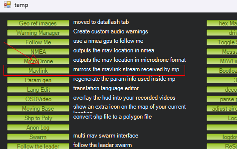
- Click Mavlink, described as “mirrors the mavlink stream received by mp”.
-
In the forwarding window, configure an outbound UDP connection:
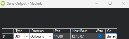
Setting Value when both applications run on the same PC Type / Protocol UDP Direction Outbound Port 14600Extra / Destination IP 127.0.0.1Write Enabled / True If your Mission Planner version uses a connection dropdown instead of a table, select UDP Client, enable Write, and enter the same destination IP and port when prompted.
- Start forwarding using the row’s Go control or the Connect button.
- Open AMC normally using its desktop shortcut or application launcher. If AMC would connect automatically to a different flight controller, disconnect that flight controller from the PC before opening AMC so the connection selection window appears.
-
In AMC’s Manual connection section, open the Port dropdown and select Add another.
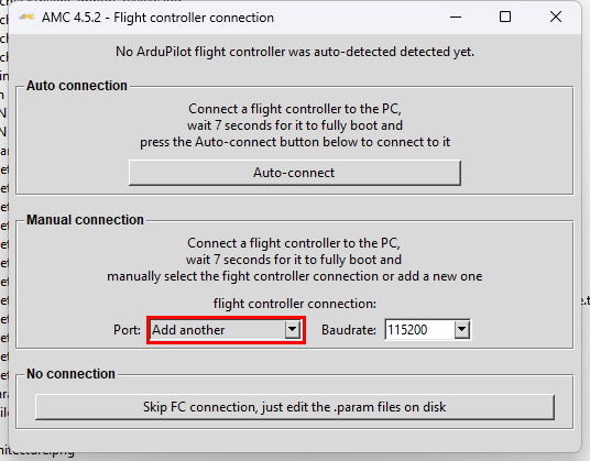
-
Enter
udpin:0.0.0.0:14600in the Flight Controller Connection dialog, then click OK. AMC will connect and retrieve the flight controller information and parameters.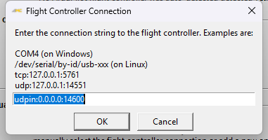
- Leave Mission Planner connected and forwarding while using AMC.
For advanced users, AMC can also be started from a terminal with an explicit listening connection,
if its command is available on PATH:
ardupilot_methodic_configurator --device="udpin:0.0.0.0:14600"
Save this connection in a desktop shortcut: On Windows, right-click the AMC desktop shortcut,
select Properties, and open the Shortcut tab. In Target, keep the existing executable
path (including its quotes), then append a space followed by --device="udpin:0.0.0.0:14600".
Click Apply, then OK. AMC will use this connection every time you launch that shortcut;
Mission Planner must still be connected and forwarding.
You can also copy the shortcut and name it AMC - Mission Planner, leaving the original unchanged for other connections. Each shortcut can have different connection, project and startup settings. See Pro Tip: Desktop Shortcuts for more examples.
Important:
127.0.0.1is Mission Planner’s destination when both applications run on the same PC.0.0.0.0tells AMC to listen on all local IPv4 interfaces; it is not a destination address. For same-PC-only listening, useudpin:127.0.0.1:14600instead.- Write must be enabled for AMC’s parameter requests and changes to reach the vehicle. Do not change the same parameters in both applications simultaneously.
- If the applications run on different PCs, set Mission Planner’s destination to the AMC PC’s IPv4 address and allow inbound UDP traffic on the selected port in that PC’s firewall.
- Use port
14600for this forwarding connection to avoid conflicts with port14550, which may already be used by Mission Planner or another MAVLink application. If port14600is already in use, select another free port in both applications. The baudrate setting does not affect UDP connections. --deviceselects the supplied endpoint directly without requiring auto-discovery. If connection fails, that endpoint remains available in AMC’s connection selector for retrying.- If AMC times out, check the vehicle connection, forwarding status, destination, matching ports, firewall and Write setting. A missing entry in the default port list does not mean a custom UDP listening endpoint is invalid.
- Bootloader firmware flashing requires a direct serial connection, not MAVLink forwarding.
Option 3: No flight controller connection 📝 For offline editing
Work with parameter files without connecting to hardware.
- ✅ Use when:
- Flight controller not available
- Pre-planning configurations
- Reviewing existing configurations
- ⚠️ Limitations:
- Cannot read current parameter values
- Cannot upload parameters
- No parameter validation against hardware
Flight Controller Info and Parameter Download
If a flight controller is connected the software will now get information from it. The information is presented in the corresponding window and at the same time all flight controller parameters are downloaded to the PC.
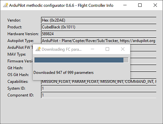
Flight controller info and parameter download
Step 2: Vehicle Configuration Directory Selection
This interface allows users to select a vehicle directory that contains intermediate parameter files for ArduPilot
if one was not specified with the --vehicle-dir command line parameter and if no configuration files were found in the current working directory.
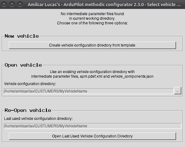
Vehicle Selection Window
It provides three main options for selecting a vehicle directory:
New
Create a new vehicle configuration directory from a template, an already configured flight controller, or a .bin log file.
When a correctly configured flight controller is connected, you can create a project directly from it:
- Click Create a vehicle project from an already configured flight controller in the New panel.
- In the creator window, select the Destination base directory and enter the Destination new vehicle name.
- The software automatically selects the empty template matching the flight controller’s vehicle type and major/minor firmware version.
- Component information and parameter values are taken from the connected flight controller.
- The FC’s default parameter values are written to
00_default.param. - If live FC values differ from the selected template/default baseline, they are written to an
xx_imported_flight_controller_parameters.paramfile for review.
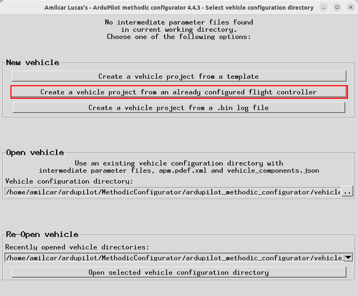
Create vehicle from an already configured flight controller
Open
Open an existing vehicle configuration directory that already contains intermediate parameter files. It’s useful for editing an existing vehicle configuration.
- Use the “Vehicle directory”
...button to select the existing vehicle directory containing the intermediate parameter files.
Re-open
Re-open the last used vehicle configuration directory.
Create a New Vehicle Configuration Directory
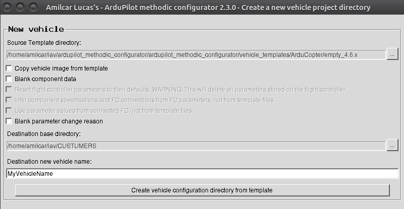
Create new Vehicle Window
Create a new vehicle configuration directory by copying files from an existing template directory. It’s useful for setting up a new vehicle configuration quickly.
- Use the “Source template directory”
...button to select the existing vehicle template directory containing the intermediate parameter files to be copied. Use the overview window to select the template that better matches the components of your vehicle.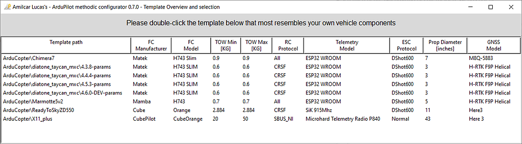
- By default, the new vehicle parameter values are taken from the source template.
But if your connected vehicle has already been correctly configured, checking the
Use parameter values from connected FC, not from template fileswill use the parameter values from the flight controller instead. - Use the “Destination base directory”
...button to select the existing directory where the new vehicle directory will be created. - Enter the name for the new vehicle directory in the “Destination new vehicle name” field.
- Click the “Create a vehicle project from a template” button to create the new vehicle directory on the base directory and copy the template files to it.
Create a New Vehicle Configuration Directory from an Already Configured Flight Controller
This workflow is intended for a vehicle whose flight controller is already configured. It creates a new project using the live flight controller values and hardware information, while selecting the matching empty firmware template automatically.
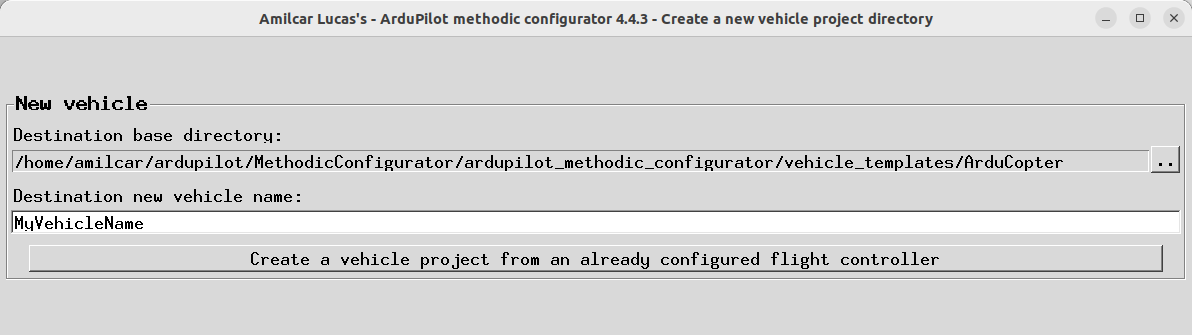
Create vehicle project from an already configured flight controller
- In the New panel, click Create a vehicle project from an already configured flight controller.
- Select the destination base directory.
- Enter a name for the new vehicle directory.
- Click the create button. AMC copies the matching empty template, substitutes the downloaded FC parameter values, and derives component specifications and connections from those values.
- AMC writes the FC’s default values to
00_default.param. Values that differ from the template baseline are written toxx_imported_flight_controller_parameters.param.
Create a New Vehicle Configuration Directory from a .bin Log File
If you have an ArduPilot .bin log file recorded by a correctly running vehicle, the software can
build a complete project from it — no physical flight controller connection required.
- Click the Create a vehicle project from a .bin log file button in the New panel.
- In the file-picker, select your
.binlog file. - The software automatically:
- Reads the vehicle type and firmware version from the log’s
VER(orMSG) record. - Selects the matching template directory (e.g.
ArduCopter/empty_4.6.x). - Names the project after the log file (without the
.binextension). - Writes the default parameter values extracted from the log into
00_default.param. - Creates
xx_imported_bin_log_parameters.paramfor any current values that differ from the template’s parameter files, giving you a clear delta to review. - Sets the firmware type and version in
vehicle_components.json.
- Reads the vehicle type and firmware version from the log’s
- You are taken directly to the Vehicle Component Editor with the firmware fields pre-filled.
Step 3: Vehicle Component Editor Interface
Here you specify the components of your vehicle, their properties and how they are connected to the flight controller.
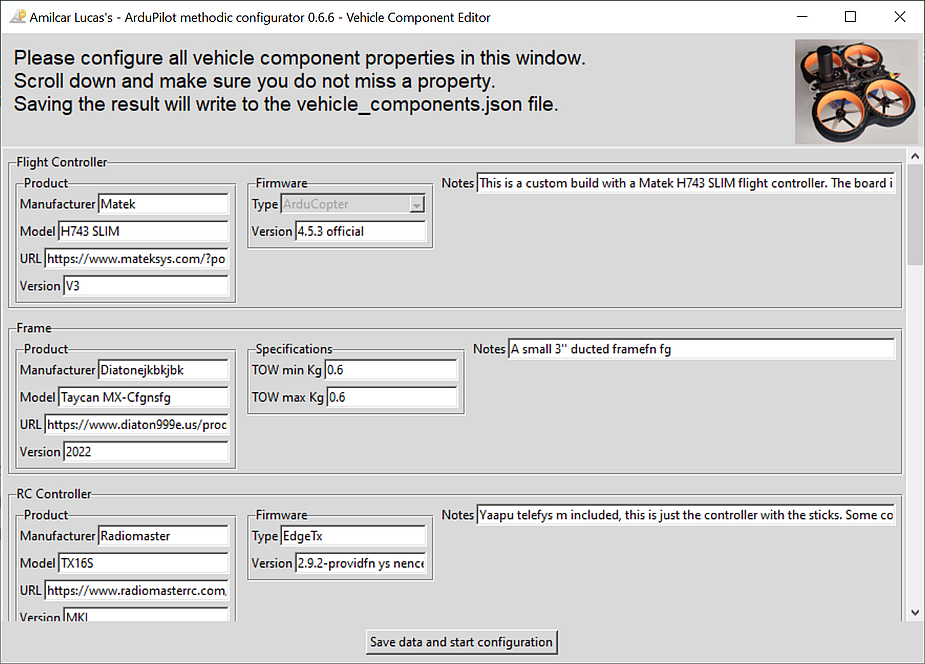

On the left with simple GUI complexity for beginners, on the right with normal GUI complexity.
Change every field to match your vehicle’s.
When finished press the Save data and start configuration button.
The software will validate your input.
If issues are found the problematic fields’ background will be marked in red color.
Correct those entries and press the Save data and start configuration button again.
Step 4: Parameter File Editor and uploader interface
Here you sequentially configure the parameters of your flight controller to meet your needs while having all the available documentation at your fingertips.
For exporting the current flight-controller values, see the Flight-Controller Parameter Export guide.

Parameter File Editor and Uploader Window (main application) in simple GUI complexity for beginners
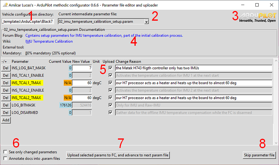
Parameter File Editor and Uploader Window (main application) in normal GUI complexity
The GUI complexity (simple or normal) is selected in the vehicle component editor window when creating a project. The normal layout is explained below, the simple layout is similar but has less elements.
When you open an existing project, AMC goes directly to the parameter editor. Use the Edit vehicle components button there to review or change the project’s component information.
Parameter editor and uploader workflow overview
Do this in a loop until the software tells you the process is finished and automatically closes:
- Read all the documentation links displayed at the top of the GUI (marked with the big red number 4),
- Edit the parameter’s New value and Reason changed fields to match your vehicle (marked with the big red number 5),
documenting change reasons is crucial because it:
- Promotes thoughtful decisions over impulsive changes
- Provides documentation for vehicle certification requirements
- Enables validation or suggestions from team members or AI tools
- Preserves your reasoning for future reference or troubleshooting
- Press Del and/or Add buttons to delete or add parameters respectively (marked with the big red number 5),
- If necessary scroll down using the scroll bar on the right and make sure you edit all parameters,
- If connected, press Upload selected params to FC, and advance to next param file (marked with the big red number 7). To advance without uploading, use Skip parameter file; this also works offline.
- Repeat from the top until the software tells you the process is finished.
1. See the Current Vehicle Directory (optional)
- this vehicle configuration directory contains the files to be edited and uploaded
2. Select an Intermediate Parameter File (optional)
- vehicle-specific intermediate parameter filenames start with two digits followed by an underscore and end in
.param - Use the
Current intermediate parameter file:combobox to select an intermediate parameter file. - The first available intermediate parameter file not named
00_default.paramwill be selected by default - If the selection changes, the parameter table will update to display the parameters from the selected file.
- The sequence is defined by the order of the intermediate parameter files in the vehicle configuration directory.
For more details on intermediate parameter files, see Intermediate Parameter Files.
3. About information and help links (optional)
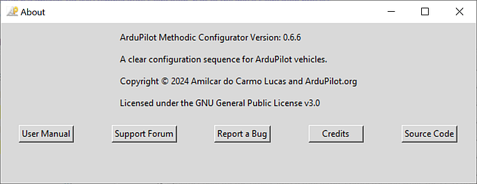
When you click the ArduPilot logo the following window will appear:
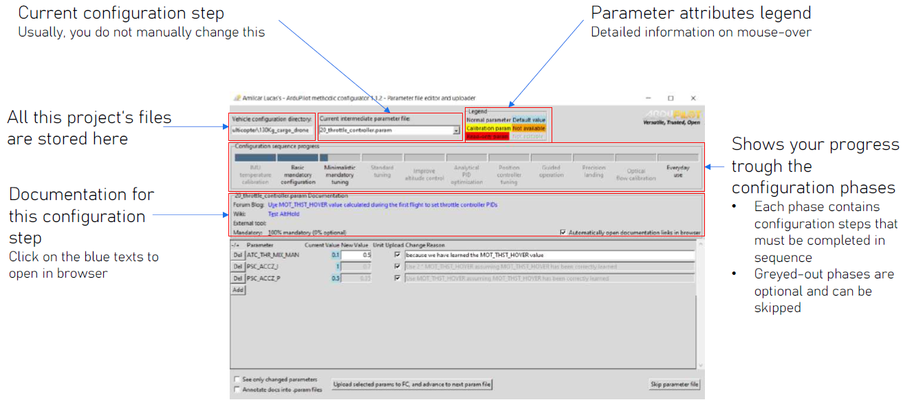
4a. Configuration sequence progress bar
This segmented bar shows the progress in the vehicle configuration sequence.
The progress bar is updated automatically when you upload an intermediate parameter file to the flight controller or
select a different intermediate parameter file in the Current intermediate parameter file: combobox above it.
The steps are grouped into phases and optional phases are greyed-out.
There are mouse-over hints for each phase.
4b. Viewing Documentation
- Click on the documentation labels to open the corresponding documentation in a web browser.
- Documentation is split into four categories:
- Blog Post - ArduPilot’s forum Methodic configuration Blog post relevant to the current file
- Wiki - ArduPilot’s wiki page relevant to the current file
- External tool -External tool or documentation relevant to the current file
- Mandatory - Mandatory level of the current file:
- 100% you MUST use this file to configure the vehicle,
- 0% you can ignore this file if it does not apply to your vehicle
- Hover over the labels to see tooltips with additional information.
5. Editing Parameters
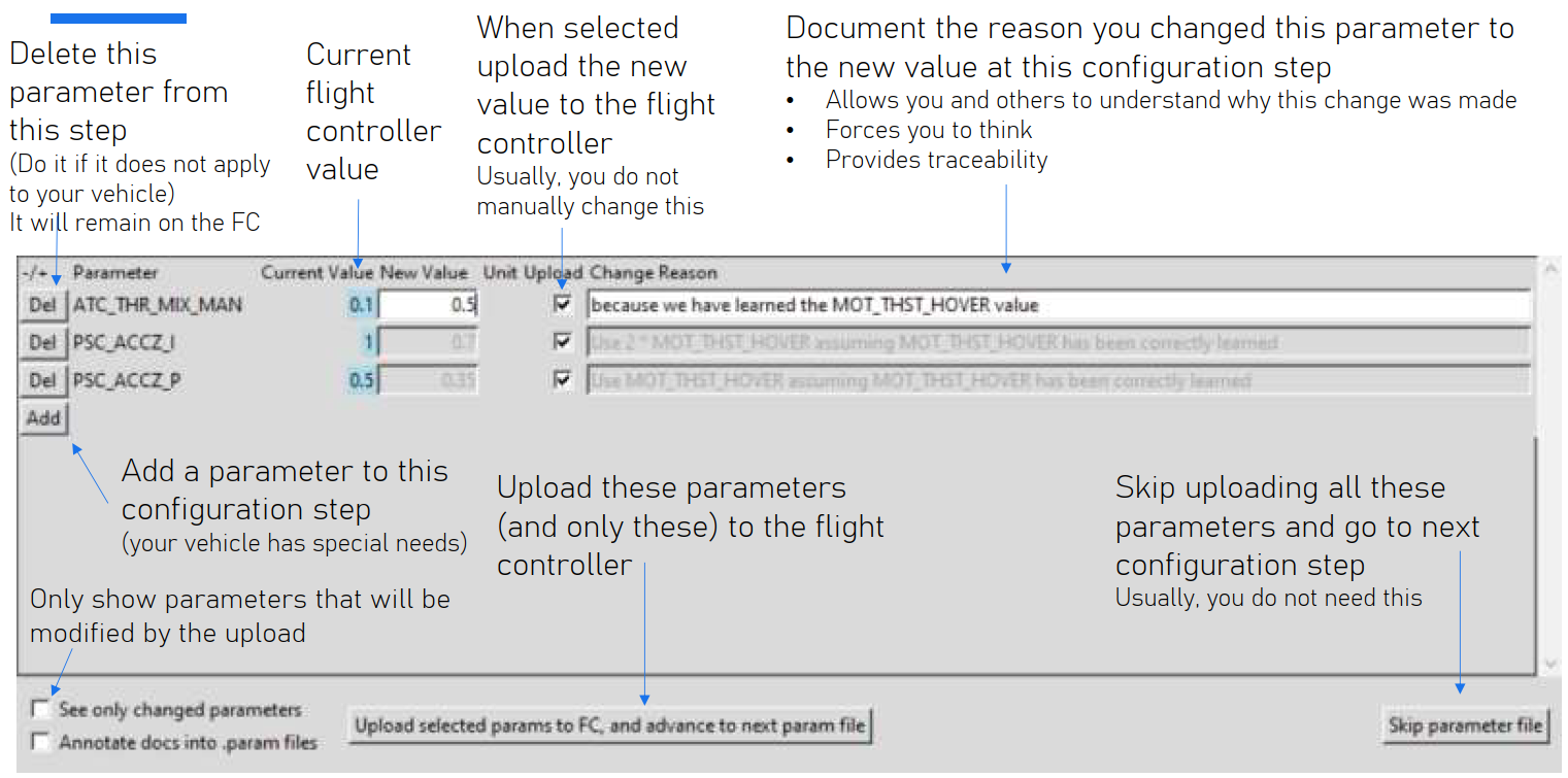
- The parameter table presents the parameters in the current intermediate parameter file
- The first column is a
Delbutton that deletes the parameter in this row from the current intermediate parameter file. - The second column is the ArduPilot parameter name used in that row.
- ReadOnly parameters are presented on a red background🟥, they should not be present in an intermediate configuration file because under normal conditions they can not be changed
- Sensor calibration parameters are presented on a yellow background🟨, they are vehicle-instance dependent and can NOT be reused between similar vehicles
- The current parameter value downloaded from your flight controller is in the
Current Valuecolumn.- Not available parameter values are presented as
N/Aon an orange background🟧 - Parameters that have the default parameter value are presented on a light blue background 🟦
- Not available parameter values are presented as
- The new value is the value in the intermediate file and will be uploaded to the flight controller.
You MUST change the value to meet your needs. The provided values in the
vehicle_templatedirectory are just examples.- parameters that should not be changed by the users, or are derived from information in the component editor are greyed out and can not be edited.
- bitmask parameters are editable in two ways:
- Decimal - enter the decimal value of the bitmask as you would with any other parameter.
- Bitmask - double-click the parameter value with the mouse and a window will popup where you can edit the individual bits in the bitmask.
- In the parameter table, you can edit the
New ValueandChange Reasonentries for each parameter. - You MUST edit the
Change Reasonso that other users understand why you changed the parameter to that particularNew value - Check the
Uploadcheckbox to select parameters to be uploaded to the flight controller - Hover over the labels to see tooltips with additional information.
- The entire ArduPilot official parameter documentation is available on the tooltip, no need to use a browser to search for it.
- The
Addbutton adds a parameter to the current intermediate parameter file.
6a. Focus on the changed parameters (optional)
- You can focus on the changed parameters by ticking the “See only changed parameters” checkbox
- Usually, you want to see all parameters and look at their mouse-over tooltips to decide if and how you want to change them
6b. Annotate parameter metadata information into the parameter files (optional)
Annotate parameter metadata information into the parameter files in the form of comments preceding the respective parameter. It will create bigger and harder-to-compare parameter files but is more suitable for text editor editing.
7. Uploading Parameters to the Flight Controller
- You can also jump to a particular file using the Combobox as explained in 2. Select an intermediate parameter file
- After editing parameters, click the
Upload selected params to FC, and advance to next param filebutton to upload the (Uploadcheckbox) selected parameters to the flight controller. - All parameters’
New ValueandChange Reasonwill be written to the current intermediate parameter file, irrespective of theUploadcheckboxes - The software will then:
- upload the selected and changed parameters to the flight controller
- reset the flight controller if necessary for the new parameter values to take effect
- upload the parameters again, because before the reset some parameters might have been not visible/uploadable
- download all the parameters from the flight controller, and validate their value
- if some parameters fail to upload correctly it asks the user if he wants to retry
- The software will then advance to the next parameter file.
8. Skipping to the Next Parameter File (optional)
- If you want to skip the current parameter file without uploading any changes, click the
Skip parameter filebutton.
9. Completing the Configuration Process
Once all the intermediate parameter files have been processed, the ArduPilot Methodic Configurator will display a summary message box.
In other words when the last available intermediate parameter file is selected (see
2. Select an Intermediate Parameter File) and either
Upload selected params to FC, and advance to next param file or Skip parameter file button is pressed.
This message box provides a comprehensive overview of the configuration process, including the number of parameters that were kept at their default values,
the number of non-default read-only parameters that were ignored, and the number of non-default writable parameters that were updated.
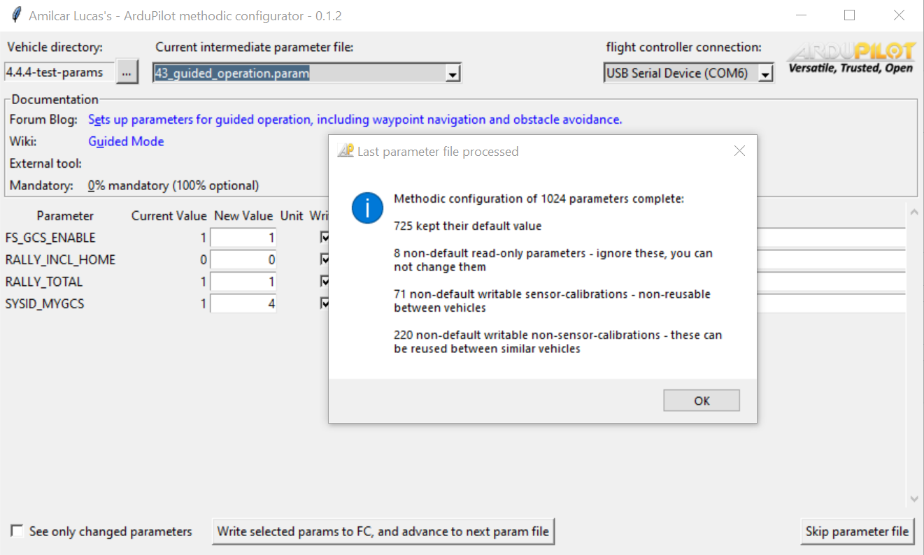
The summary message box will also categorize the writable parameters into four groups:
pie title Summary files example
    "Unchanged parameters" : 728
    "Non-default read-only parameters - non-default_read-only.param" : 8
    "Non-default writable sensor calibrations - non-default_writable_calibrations.param" : 71
    "Non-default writable IDs - non-default_writable_ids.param" : 3
    "Non-default writable non-sensor-calibrations, non-IDs - non-default_writable_non-calibrations_non-ids.param" : 217
    "Reusable parameters, including defaults - reusable.param" : 945
If the diagram above does not display correctly look here
-
Unchanged parameters: These parameters are left unchanged and are displayed on a light blue background 🟦.
-
Non-default read-only parameters: These parameters are read-only and cannot be changed. They are typically related to system configurations that can not be modified and are displayed on a red background 🟥.
-
Non-default writable sensor calibrations: These parameters are vehicle-instance dependent and cannot be reused between similar vehicles. They are typically related to sensor calibration and should be adjusted for each vehicle and are displayed on a yellow background 🟨.
-
Non-default writable IDs: These parameters are vehicle-instance dependent and cannot be reused between similar vehicles.
-
Non-default writable non-sensor calibrations, non-IDs parameters: These parameters can be reused between similar vehicles. They are not related to sensor calibration and are generally applicable to a range of vehicles with the same configuration.
After the summary message box is displayed, the application will write the summary information into separate files for easy reference and documentation. These files include:
complete.param: Contains all parameters contained in the flight controller.non-default_read-only.param: Contains all non-default read-only 🟥 parameters. You can ignore these.non-default_writable_calibrations.param: Contains all non-default writable sensor calibration 🟨 parameters. These are non-reusable.non-default_writable_ids.param: Contains all non-default writable IDs. These are non-reusable.non-default_writable_non-calibrations_non-ids.param: Contains all non-default writable non-sensor-calibration, non-IDs parameters. These are reusable across similar vehicles.reusable.param: the same as above, but includes (non-read only, non-calibration, non-IDs) default values
The summary files provide a clear overview of the changes made.
The files are also automatically zipped into a file with the same name as the vehicle directory, inside the vehicle directory.
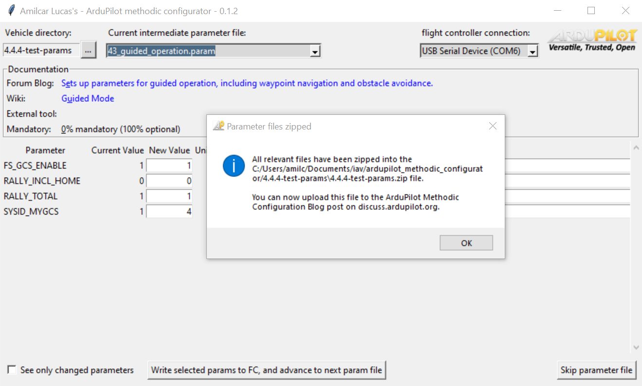
Once the summary files are written, the application will close the connection to the flight controller and terminate.
Configuring multiple similar vehicles
- Create a separate vehicle configuration directory for each vehicle with a descriptive name
- Copy the
*.param,*.json,*.jpgfiles to each directory - Connect the PC to the vehicle flight controller and open the respective vehicle configuration directory in AMC
- Edit files to match each vehicle’s specific requirements
When manufacturing multiple vehicles of the same model, you can reuse most configuration files across instances. If you maintain high-quality standards that result in the production of multiple, nearly identical vehicles, only three parameter files are vehicle-specific:
03_imu_temperature_calibration_results.param14_mp_setup_mandatory_hardware.param32_inflight_magnetometer_fit_results.param
Command Line Usage
The ArduPilot Methodic Configurator can be started from the command line. The command line interface provides several options to customize the behavior of the tool.
To use the command line interface, execute ardupilot_methodic_configurator on the command line.
Here is a list of command line options:
--skip-check-for-updates: Skip check for software updates before starting the software. Default is False.--baudrate BAUDRATE: MAVLink serial connection baudrate to the flight controller. Default is 115200--device: The MAVLink connection string to the flight controller. It defaults to autoconnection to the first available flight controller.--vehicle-dir: The directory containing intermediate parameter files. Defaults to the current working directory. When explicitly supplied with--bin-log, it is the complete destination directory for the new project.--bin-log PATH: Create a new vehicle project from an ArduPilot.binlog file without connecting to a flight controller. By default, the new project is created in the default vehicles directory. An explicitly supplied--vehicle-dirinstead selects the complete destination directory.-
--template-dir PATH: Optional template directory to use with--bin-log. If omitted, AMC uses the empty template matching the vehicle type and major/minor firmware version extracted from the log.Bundled empty templates currently include:
ArduCopter/empty_4.5.xArduCopter/empty_4.6.xArduCopter/empty_4.7.xArduPlane/empty_4.7.x
These are the currently supported automatic defaults; for other vehicle and firmware combinations, use
--template-dirto provide a compatible template explicitly. --n: Start directly on the nth intermediate parameter file (skip previous files). The default is 0.--loglevel: The logging level (DEBUG, INFO, WARNING, ERROR, CRITICAL). The default is INFO.-tor--vehicle-type: The type of the vehicle. Choices are ‘AP_Periph’, ‘AntennaTracker’, ‘ArduCopter’, ‘ArduPlane’, ‘ArduSub’, ‘Blimp’, ‘Heli’, ‘Rover’, ‘SITL’. Without--bin-log, the default is ‘ArduCopter’. With--bin-log, the type is derived from the log unless-tis given. With--bin-log, this value validates both the vehicle type reported by the log and the selected template, and records the explicitly selected type in the new project (for example,Heliuses the compatibleArduCoptertemplate). SITL and AP_Periph are pseudo-types and cannot be used with--bin-log.-ror--reboot-time: Flight controller reboot time. The default is 7.-vor--version: Display version information and exit.
Example Usage Scenarios
Basic Usage (Auto-detection)
# Simplest form - auto-detect flight controller and use current directory
ardupilot_methodic_configurator
Specific Connection and Directory
# Windows - specify COM port and project directory
ardupilot_methodic_configurator --device="COM3" --vehicle-dir="C:\MyQuadcopter"

# Linux - specify USB device and project directory
ardupilot_methodic_configurator --device="/dev/ttyUSB0" --vehicle-dir="/home/user/MyQuadcopter"

# Network connection (SITL or network-connected FC)
ardupilot_methodic_configurator --device="tcp:127.0.0.1:5760" --vehicle-dir="/path/to/params"
Create a Project from a .bin Log
# Use the empty template inferred from the vehicle type and firmware in the log
ardupilot_methodic_configurator --bin-log="C:\logs\flight.bin"

# Use a specific template directory instead of the inferred empty template
ardupilot_methodic_configurator --bin-log="C:\logs\flight.bin" --template-dir="C:\templates\Holybro_X500"
After the project is created from the log, AMC continues through the normal GUI workflow: the Vehicle Component Editor opens first, followed by the parameter editor and uploader.
Start with an Existing Project
# Existing projects open directly in the parameter editor
ardupilot_methodic_configurator --vehicle-dir="C:\MyDrone"

# Start from specific parameter file (skip earlier steps)
ardupilot_methodic_configurator --n=5 --vehicle-dir="C:\MyDrone"

# Combine options when opening an existing project
ardupilot_methodic_configurator --device="COM3" --vehicle-dir="C:\MyDrone" --n=3
Different Vehicle Types
# Fixed-wing aircraft
ardupilot_methodic_configurator -t ArduPlane --vehicle-dir="C:\MyPlane"

# Rover/boat
ardupilot_methodic_configurator -t Rover --vehicle-dir="C:\MyRover"

# Helicopter
ardupilot_methodic_configurator -t Heli --vehicle-dir="C:\MyHeli"
Debugging and Development
# Enable debug logging for troubleshooting
ardupilot_methodic_configurator --loglevel=DEBUG --vehicle-dir="C:\MyDrone"

# Skip update check (for offline use)
ardupilot_methodic_configurator --skip-check-for-updates --device="COM3"

# Combine debugging options
ardupilot_methodic_configurator --loglevel=DEBUG --skip-check-for-updates --device="COM3"
Pro Tip: Desktop Shortcuts
Create multiple desktop shortcuts for different projects or connection settings.
On Windows, copy an existing AMC shortcut, rename it, then right-click it and select
Properties → Shortcut. Append the desired options to Target, after the existing
executable path and a separating space. Keep any quotes around the executable path.
Click Apply, then OK to save the options for every launch of that shortcut.
If an option such as --device is already present, replace its value rather than adding it twice.
For example, a shortcut named AMC - Mission Planner can append
--device="udpin:0.0.0.0:14600" to use the
Mission Planner forwarding connection.
Keep a separate shortcut without this option for automatic connection detection.
Shortcut 1 (MyQuadcopter):
Target: ardupilot_methodic_configurator.exe --device="COM3" --vehicle-dir="C:\MyQuadcopter"
Shortcut 2 (MyPlane):
Target: ardupilot_methodic_configurator.exe --device="COM4" --vehicle-dir="C:\MyPlane" -t ArduPlane
For more detailed information on command line options, run:
ardupilot_methodic_configurator --help
This will show a list of all available command line options along with a brief description of each.
For command line completion setup, see the Installation Guide.
Speed up software start
To speed up the startup of the ArduPilot methodic configurator, consider the following tips, presented from most to least effective:
All of these can be either added in the command line as a parameter, or in the “properties > link > target” of the desktop icon. Use an empty space to separate each option.
--device <devicename>this explicitly connects to <devicename> skipping the auto-detection process.--vehicle-dir <vehicle-directory>this explicitly looks for project files in <vehicle-directory> saving you the trouble to manually select it in the GUI.--n <number>this will skip directly to step number <number> so that you do not need to skip the previous steps--skip-check-for-updatesthis saves very little time on startup, but you can skip it using this.
Pro tip: create multiple desktop icons, each one with a different project and or configuration.
Troubleshooting
Common Issues and Solutions
Connection Problems
Issue: “No flight controller detected” or auto-connect fails
Solutions:
- Check physical connection: Ensure USB cable is properly connected
- Incorrect serial baudrate: If the serial baudrate is different from 115200 you must connect manually
- Wait longer: Flight controller needs 7+ seconds to boot fully
- Try different USB port: Some ports may have power/data issues
- Check USB cable: Try a different cable (data cable, not just power)
- Manual connection: Use Option 2 and select the correct COM port
- Driver issues: Install flight controller drivers if needed
Issue: “Connection lost during operation”
Solutions:
- Check USB connection: Ensure cable isn’t loose
- Restart software: Close and reopen the configurator
Parameter File Issues
Issue: “Parameter file not found” or “Invalid parameter file”
Solutions:
- Check file location: Ensure parameter files are in the correct directory
- File permissions: Verify you have read/write access to the directory
- File format: Ensure parameter files follow the correct format
- Regenerate defaults: Use
extract_param_defaultsif00_default.paramis missing
Issue: “Parameter upload failed” or “Parameter validation error”
Solutions:
- Check parameter values: Ensure values are within valid ranges
- Flight controller firmware: Verify firmware version compatibility
- Retry upload: Some parameters require multiple attempts
Component Issues
Issue: “Component validation failed”
Solutions:
- Review component settings: Check all required fields are filled
- Component compatibility: Ensure components are compatible with your flight controller
- Firmware limitations: Some components require specific firmware versions
- Documentation: Consult component manufacturer specifications
Application Issues
Issue: Software crashes or freezes
Solutions:
- Restart software: Close and reopen the configurator
- Check system resources: Ensure adequate RAM and disk space
- Update software: Check for newer version of the configurator
- Log files: Check application logs for detailed error information
- Safe mode: Try running with
--loglevel DEBUGfor more information
Issue: GUI elements not displaying correctly
Solutions:
- Display scaling: Adjust Windows display scaling settings
- Screen resolution: Ensure minimum resolution requirements are met
- Graphics drivers: Update graphics card drivers
- Compatibility mode: Try running in compatibility mode (Windows)
Getting Help
For detailed support information, troubleshooting guidance, and how to report issues, see the Support Guide.
Installation and Security Verification
For detailed installation instructions and installer security verification, see the Installation Guide.
Frequently Asked Questions
For comprehensive answers to common questions about the ArduPilot Methodic Configurator, please see our dedicated FAQ document.
The FAQ covers:
- General Questions: Internet requirements, supported vehicles, timing expectations
- Technical Questions: Parameter editing, templates, firmware compatibility
- Workflow Questions: Component editor, configuration changes, vehicle comparisons
💡 Quick Access: View Complete FAQ →
Glossary
ArduPilot: Open-source autopilot software suite for unmanned vehicles, providing autonomous flight capabilities
Bitmask Parameter: A parameter where each bit represents a different option that can be enabled/disabled independently
Component Editor: Interface for specifying vehicle hardware components and their connections to the flight controller
ESC: Electronic Speed Controller - controls motor speed based on flight controller commands
FC: Flight Controller - the main computer hardware that runs ArduPilot firmware and controls the vehicle
Firmware: The ArduPilot software program running on the flight controller hardware
Flight Mode: Different operational modes of the vehicle (Manual, Stabilize, Auto, etc.)
IMU: Inertial Measurement Unit - sensors that measure acceleration and rotation (accelerometer + gyroscope)
Intermediate Parameter File: A .param text file containing a subset of parameters for a specific configuration step
MAVLink: The communication protocol used between ground control software and flight controllers
Parameter: A configuration value that controls flight controller behavior (over 1200 available)
Parameter Documentation: Detailed descriptions of what each parameter controls, including valid ranges and units
Parameter Template: A pre-configured set of parameter files for a specific vehicle type or configuration
PID Controller: Proportional-Integral-Derivative controller used for flight stabilization and navigation
SITL: Software In The Loop - ArduPilot simulation environment for testing without hardware
Template Directory: Folder containing pre-configured parameter files that can be copied for new vehicle setups
Vehicle Instance: A specific physical vehicle with unique calibration parameters (vs. reusable template parameters)
Vehicle Type: The category of vehicle (ArduCopter, ArduPlane, etc.) that determines available parameters and features